Drawing Sliver Coiling
When coiling sliver into the can it is important
to maintain: a smooth compacted sliver with low hairiness, fill the can in the
correct manner and minimize dust / trash accumulations in the coiler tube.
Ø Coiler tube
The form of the coiler tube
has been developed to enable the sliver to move with minimal interference into
the can. The tube is normally made of stainless steel, which is wear resistant
and suitable for most fibers. There are a very few exceptions in which the
sliver is not compatible with the frictional characteristics of steel, and will
not freely slide through the tube. In this case it may be necessary to use a
brass coiler tube.The coiler tube and plate have to be selected to suit the
sliver weight and the diameter of the sliver can.
Ø Coiler tube inside diameters
To obtain a smooth and compacted sliver the
coiler tube should be as small as practicable. If the tube diameter is too
large for the sliver, the sliver will have a tendency to:
·
Be hairy,
·
create
difficulties during withdrawal from the can,
·
have a
reduced sliver cohesion.
·
detailed
Rieter recommendations can be found in the machine manual
Ø Sliver deposit
Depending upon the sliver can size, the sliver
is coiled either “over center” in cans 225 to 600 mm diameter or “under center”
(some references use “onto the center”) in cans 800 to 1000 mm diameter.
Ø Coiler settings
To maintain good quality
coiling of the sliver, the following points of the coiler have to be correctly
set:
Coiler speed depending upon
material and sliver weight. The speed must not be excessive and stretch the
sliver, nor too slow and lay the sliver unevenly in the can location (eccentricity) to build a column
diameter 10 mm smaller than the can’s inside diameter. This should be checked
when the can is 75 % full,Can table speed to adjust the coil spacing so that
the sliver coils are side by side, not overlapping and not spaced apart.Length of
sliver in a full can must not be excessive. An overfilled can creates problems
of sliver disturbance and scuffing which leads to drafting problems at the
subsequent processes.
·
The can
condition has to correct, damaged and out-of round cans cause many problems and
a deterioration of sliver quality.
·
The cans
must be the required size and set relative to the coiler plate.
·
The can
spring length and pressure must be correct for the material being processed.
·
The
coiling conditions have to be checked and, if necessary adjusted, with any
change of: Sliver weight, - Material,
Coiler speed
Check coiler speed
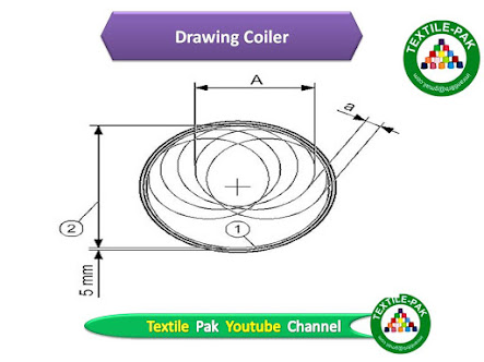
The coiler speed is correct. The sliver (2)
leaves coiler plate at back of the kidney-shaped.
The coiler speed is too high. The sliver is
pulled to the inside of the coiler exit.
The sliver is stretched, the coils will be
deformed and periodic draft faults may occur.
Ø Correct coiler speed
Coil
diameter (A) is evenly round. Distance (a) between the coils (A) remains
uniform around the can.The form of the sliver column (2) is evenly round and 5
mm clear of the can side (1)
Coiler
Speed Too Low
The coils
are too wavy.
The distance (a) between the coils (A) is
relatively uniform.
The Diameter of the sliver column (2) is too
large and is equal to or greater than the inside diameter of the can (1).
Ø Coiler speed too high
Sliver coils (A) are out of round and are not
consistent. The coils are drop shaped with the tip pointing toward the can
inside wall (1) The distance (a) between the coils varies from one coil to
another. The sliver column (2) is out of round. The sliver column (2) is too
small and the clearance between the column and the inside of the can is more
than 5 mm.
Coiler speed correct
Sliver coils per can revolution
The
sliver coils per layer is obtained by dividing the speed (rpm) of the coiler by
the rotational speed of the can table. With larger diameter cans the number of
coils per layer increases to maintain optimal coiling and can filling.
nD =
Relationship of coiler rpm to can table rpm
nD =
coiler rpm
can table
rpm
The
following can be used as a guideline
Ø Can eccentricity
The outside diameter of the sliver column is primarily established by the relative positions of the centers of the coiler and the can table. This distance is referred to as the eccentricity. If the can table is moved to reduce the eccentricity the sliver column will be reduced, and conversely the column will be increased if the table is moved to increase the eccentricity. The setting of the can table eccentricity is normally not changed.
However, it may be necessary to make a re- adjustment if there is a change to fibers of greatly different bulk characteristics, such as cotton to acrylic fibers.


No comments:
Post a Comment